Under Construction 
Contents: CB | Transmission Line | SWR | Mobile | Manufacturers - Suppliers
CB Antennas:
The most efficient mobile antenna is the 1/4 wave length (102-106") whip.
Antennas can be shortened by "loading" (placing a coil on the antenna).
The most efficient of the shortened mobile antennas is the continuously loaded mobile antenna. It is usually a fiberglass rod wrapped up its whole length with a copper wire or flat ribbon.
A common CB antenna today measures about 4' tall. One type uses a fiberglass rod and winds the wire around the rod, with the bulk of the wire being closely spaced at the top of the antenna. This is called a top loaded whip.
An antenna with a load coil in the middle is the next most efficient.
Performance can be inproved with two antennas. Co-Phasing antennas using two identical antennas, feed in-phase. They should be 1/4 wavelength (9 ft.) apart.
The body of the vehicle acts as a ground plane. Radiation is stronger towards the ground plane side of the antenna. i.e. an antenna in the back of the vehicle radiates more towards the front.
CB Frequencies:
| Channel | Freq | Wave
Length (1) | 1/4 wave (2) |
| 1 | 26.965 | 11.12 m. | 104.1 in. | |
| 40 | 27.405 | 10.94 m. | 102.5 in. |
Note: The above table uses 1. the speed of an electromagnetic field in a vacume for wave length and 2. the speed of electricity in copper wire for the 1/4 wave.
You will see two numbers for calculating 1/2 wavelength.
1. 300/freq. (MHz) - based on speed of light in a vacume (2.998 * 108 m/sec.)
2. 468/freq. (MHz) - based on velocity (feet per sec.) of propagation of the wave in an antenna.
See Electromagnetic Principles
What if you mount the antenna on a spring? Is the spring part of the antenna?
Transmission Line - Coax:
RG-58/U, a very common 50 ohm cable used for mobile antenna installation.
Over 150 ft. you should use RG-8/U which has lower loss.
Get a good brand, e.g. Belden.
See Coaxial Cable.
Notes:
Probably 75% of low power radio stations will want to use a 150 watt transmitter and a pair of circularly polarized antennas. (prometheusradio.org)
Tuning - SWR:
Regardless of the type, style, size, shape, or brand of antenna you choose, it must be tuned to your particular vehicle, in the particular location that you've installed it, using an SWR meter ($20 at Radio Shack).
If there is a mismatch, it can cause problems with your radio and antenna, and will degrade performance.
An SWR of 1:1 across all channels is ideal (supposedly only attainable in the lab); ≤1.5:1 is the optimal to shoot for in real world installations; 2:1 is good (10% of the power being reflected back from the antenna.); 3:1 is poor; 4:1 or greater could damage your equipment!
The fact is that the impedance transformations along a transmission line lead to sections with higher and lower voltage, and higher and lower current, called standing waves because the highs and lows are spaced in wavelengths at the operating frequency, and do not move along the cable. The voltage standing wave ratio is simply the ratio between the voltage at the highest and lowest point of such a standing wave! This ratio happens to be equal to the ratio between the highest and lowest current, and also is equal to the ratio between the cable impedance and the load impedance! Which means that it is also equal to the ratio by which the current-to-voltage ratio departs from the correct value it should have for that cable!
Imagine the transmitter sending a wave up the cable, in the proper voltage to current ratio. This will be a traveling wave. Now, the load will reflect a portion of this wave if it is not of the same impedance as the cable. This reflected wave will travel back to the transmitter, creating interference patterns along the cable, resulting in the standing wave of voltage and current maxima and minima. While one wave travels up and the other travels down the cable, the interference patterns stay fixed. This is just another way to look at exactly the same phenomenon.
Defective or inferior components, bad installations and antennas not tuned to the specific location on the Jeep increases the SWR.
| Transworldradio SWR Rule |
|
| Lengthening: |
The antenna is too short and must be lengthened if:
the SWR reading at the low end of the amateur band is 5:1 and decreases to 2.5:1 at the high frequency end of the same band. |
| Shortening |
The antenna is too long and must be shortened if:
the SWR reading at the low frequency end of the amateur band is 2.5:1 and increases to 5:1 ant the high frequency end of that same band. |
An HF SWR meter is not recommended for VHF use, but if it calibrates to full scale in the set position, the readings may be accurate.
Your CB Radio base antenna system may be erected 20 feet higher than the highest point of the building or tree on which it is mounted; however, the highest point of the antenna must not be more than 60 feet above the ground. There are additional restrictions on an antenna system located near an airport. Consult FCC Laws Part 95, Subpart D for your particular situation.
Connectors:
N-type connectors are better for 440 MHz
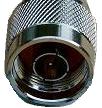 
Most Amateur radios come with UHF (PL-259 / SO-239) connectors
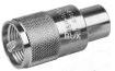 
See: Antenna Connectors - Plugs - cables
Loss with UHF connectors over 432 MHz:
UHF connectors were designed in the 1930's by Amphenol for use in systems from 0.6 - 300 MHz.
At the time 300 MHz was considered high frequency. Current thinking is they will result in around 1/2 dB loss per connector and a whole lot of VSWR at 432 MHz. K2RIW dosent agree; see below.
In "The UHF type connector under network analysis" at qsl.net they say:
"Before wrapping things up I must admit that the UHF type barrel connector employed here was of fairly poor quality, as one would find in most hobby type outlets. I suspect that it contributed significantly to the poor results gained but we should also keep in mind that good quality connectors of the UHF type are not easily found. In real world terms the 0.2 dB Insertion loss at 144 MHz would be a transmission loss of more than 1 Watt from a 25 Watt input at 144 MHz. The real bad news is at 432 MHz where we see a loss in the order of 1.0 dB, this equates to a transmission loss of around 6 Watts with 25 Watts input. This phenomenon is of course due to the Impedance "bump", the power is not actually lost but reflected in the transmission lines.
Unfortunatly most multi-band radios come with UHF connectors.
AT Coax Impedances, Losses, and the Maligning of UHF, Dick Knadle, K2RIW says this is an "old wives tale".
The mated UHF connector has an internal connector length of less than 0.9 inches. A free space wavelength at 432 MHz is 27.3 inches. The 0.9 inches represents a phase length of 11.9 degrees. If I plot this up on a Smith Chart that's an input VSWR of 1.16:1, which gives a worse case reflected-power-caused transmission loss of 0.024 dB.
It's User Friendly Assembly -- There are probably twice as many amateurs who can do a good job of installing a UHF connector on an RF cable, as compared to a Type N connector. The proper installation and WX proofing of a Type N connector requires considerable finesse and experience. It's almost an art form.
See Also:
J-Pole Amateur radio antenna for 2 m
Electromagnetic Spectrum
Electromagnetic Principles
The Ultimate Guide to 11 Meter CB Antennas at signalengineering.com
CB Antenna Primer
FAQs at Firestick.com
CB Antenna Basics at jeephorizons.com
Antenna Connectors - Plugs - cables
What is SWR
Glossary of Antenna Terms
Transmission Lines for Dummies
Fabricating CB Antennas
Antennas at Tower Electronics
Standing Electrical Waves Demonstration (The Theory of Resonance)
Electronics 101 at cabl.com
Antenna FAQ
VHF/UHF Antenna Types at Bexcom
"The UHF type connector under network analysis" at qsl.net
Coax Impedances, Losses, and the Maligning of UHF
Auto Installation:
Guidelines:
At least 1/2 and preferably 2/3 of the antenna should be above the roof.
Mounts:
NMO UHF PL-259 SO-239
See Connectors in technology.
- SWR
- Standing wave ratio. a ratio of maximum voltage or current to minimum voltage or current (everything from the coaxial connector at the radios output to the tip of the antenna).
Manufacturers:
CB:
Firestik Antenna Company,
Wilson
K40, Tram
Ham:
 OPEK, OPEK,  arrow, arrow,
 diamond, Lakeview (Hamstick). diamond, Lakeview (Hamstick).
 , ,  and and  distributed by NCG (NatCommGroup) distributed by NCG (NatCommGroup)
Radiall/Larsen
Contacts:
Mounting considerations:
Radiataion Safety:
FCC rules require that a transmitter radiating a hundred watts ERP be at least 13.5 feet away from where anyone hangs out for more than a few minutes at a time.
Installation Guide
Loction:
A vertical transmitting antenna mounted close to the ground can wipe out cable TV reception, FM band signals and make VCRs go on the blink, while some HIFI sets may go from Mozart or Heavy Metal.
Trees:
Trees have been known to work. There are some stations that have installed antennas in the tops of trees. A few issues come into play. One is the proximity to the leaves of the tree. Antennas work best when they clear any other object by at least a wavelength or two, which in FM is 20 to 24 feet. Leaves, particularly, have a lot of water and a lot of reflective surface, and can significantly throw off the tuning of your antenna. If you use a tree, you will have to make an alternate arrangement for grounding, since the tree itself will not conduct electricity to ground like a metal mast would.
Tree antennas shouldn't be overlooked as stealth antennas. A vertical wire running vertically up the trunk of a tall tree is nearly invisible. Resistive losses in the nearby tree trunk smooth antenna reactance variations with frequency and greatly increase the antenna's bandwidth. If used with buried ground radials tree verticals function reasonable well transmitting despite losses in the tree trunk and they make excellent wideband receiving antennas.
Suppliers:
Antennas at: RigPix |
w6ze.org (Orange County ARC) |
Ham Radio Outlet | V I S Amateur Supply.
Universal Radio: Mobile,
Amateur HT,
Amateur Base,
Citizens Band
NCG (NatCommGroup) North American Distributor for , and brand antenna products from Japan.
HT antennas: (Dual Band, Tri-Band)
Mobile Antennas: (Dual-Band, Tri-band), Price List (all products)
COMMunications PARTS: Mobile, Base
Books:
"Practical Antenna Handbook" by Joseph Carr
See Also:
Emergency Communications Vehicle Recommendation for Jeep Wrangler
Hang 'em High: Options for antennas, masts and towers at Prometheus Radio Project
Help in Choosing the Right VHF Antenna
Installation Guide
Antenna Connectors - Plugs - cables
Return to Amateur Radion in Hobbies, Amateur Radio or Personal Radio in Products.
last updated 30 Sep 2006
|  Hobbies